- My Portal
- Search
- Advise & Solutions
- Industries
- Calendar
- Solicitations
- Research
- tab 9
- tab 10
- tab 11
- tab 12
- tab 13
- tab 14
- tab 15
- tab 16
- tab 17
- tab 18
- tab 19
- tab 20
Catalog & Support
-
Instrumentation & Services
Find Products, Service Centers, Dealerships, Manuals, and more.
-
Business Services
Companies & Community
Support
Resources
_________________________ This section requires a Corporate membership _________________________
Products & Services Wanted
News
- Article
- Publisher
- Contact
- tab 8
- tab 9
- tab 10
- tab 11
- tab 12
- tab 13
- tab 14
- tab 15
- tab 16
- tab 17
- tab 18
- tab 19
- tab 20

The electrical power issues that most frequently affect industrial plants include voltage sags and swells, harmonics, transients, and voltage and current unbalance.
In a balanced three-phase system, the phase voltages should be equal or very close to equal. Unbalance or imbalance is a measurement of the inequality of the phase voltages. Voltage imbalance is the measure of voltage differences between the phases of a three-phase system. It degrades the performance and shortens the life of three-phase motors.
The impact of the transients on motors can be severe. Motor winding insulation can break down, which can then lead to costly early motor failure and unplanned downtime.
Testing for transient voltage in motors
Transient voltages—temporary unwanted spikes or blips of voltage in an electrical circuit—can come from any number of sources either inside or outside of an industrial plant.
Adjacent loads turning on or off, power factor correction capacitor banks or even distant weather can generate transient voltages on distribution systems. These transients, which vary in amplitude and frequency, can erode or cause insulation breakdown in motor windings
Finding the source of these transients can be difficult because of the frequency of the occurrences and the fact that they symptoms can present themselves in different ways. For example, a transient may appear on control cables that do not necessarily cause equipment damage directly but may disrupt operations.
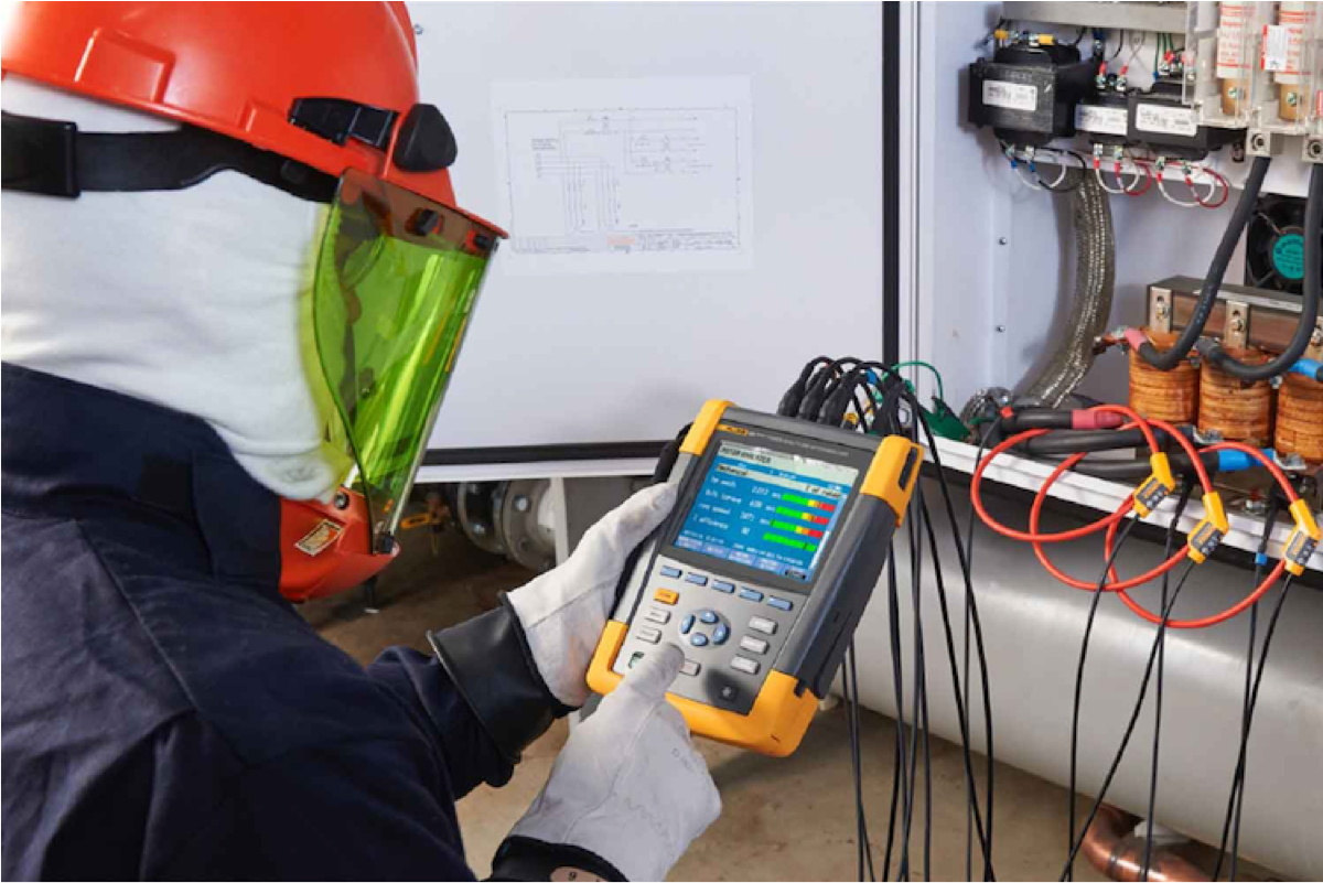
A good way to identify and measure transients is to use a three-phase power quality analyzer with a transient function, such as the Fluke 438-II Power Quality and Motor Analyzer. The transient function on the meter is set to great than 50V above the normal voltage. The meter’s display will then show the potentially problematic voltage above 50V – the transients.
If no transients are found in an initial measurement, it is a good practice to measure and log the power quality over time with an advanced industrial power quality logger, such as the Fluke 1750 Three-Phase Power Quality Logger.
What causes unbalanced voltage?
An unbalanced three-phase system can cause three-phase motors and other three-phase loads to experience poor performance or premature failure because of the following:
- Mechanical stresses in motors due to lower than normal torque output
- Higher than normal current in motors and three-phase rectifiers
- Unbalance current will flow in neutral conductors in three-phase wye systems
Voltage unbalance at the motor terminals causes high current unbalance, which can be 6 to 10 times as large as the voltage unbalance. Unbalanced currents lead to torque pulsation, increased vibration and mechanical stress, increased losses, and motor overheating. Voltage and current unbalances could also indicate maintenance issues such as loose connections and worn contacts.
Unbalance can occur at any point throughout the distribution system. Loads should be equally divided across each phase of a panelboard. Should one phase become too heavily loaded in comparison to others, voltage will be lower on that phase. Transformers and three-phase motors fed from that panel may run hotter, be unusually noisy, vibrate excessively, and even suffer premature failure.
How to calculate voltage unbalance
The calculation for determining voltage unbalance is straight forward. The result is the percentage unbalance and can be used to determine next steps in troubleshooting motor issues. There are three steps in the calculation:
- Determine the voltage or current average
- Calculate the largest voltage or current deviation
- Divide the maximum deviation by the average voltage or current and multiply by 100 % unbalance = (Max deviation from average V or I/average V or I) x 100
A manual unbalance calculation is a point-in-time determination of voltage or current unbalance. A motor drive analyzer like the Fluke 438-II will show voltage or current unbalance in real time, including any variations in unbalance.

All Registered Trademarks, brand names and logos are respected and their ownership acknowledged. They are used on this website for information and reference purposes only. Test Interest doesn't assume any other implication or representation.
